O'ring Slot Design
- Parker´s O-Ring Selector is an engineering tool which offers O-ring material and size selection combined in one tool. Both are interlinked, thus ensuring the best possible combination of the calculated O-ring size and material choice.
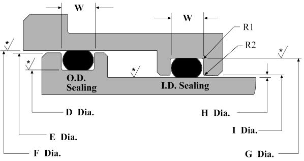
- After you have verified your nominal o-ring size functionality within your assembly, specify / design your o-ring groove/gland. Male and Female O-Ring Gland / Groove Installation For Internal Pressure tolerance the outermost surface of the o-ring gland / groove (Do) as follows.
- Slot car chassis and chassis kit products available at Professor Motor, Inc.
Generally, the larger the last two numbers the larger o-ring I.D. (inside diameter), while a larger first number indicates a larger cross-section diameter. O-rings come in many sizes, but only one shape. When using an o-ring as part of your seal design, you’ll need to design a groove where the o-ring can sit.
In this article we will see the basic difference between slot , holes, groove, and keyways.
1. Hole: circular cutout, either through the material or to a blind depth.
Types of Hole :
They are different types of holes that are mentioned below.
1.Simple Hole
2.Counter board
3.counter sunk
4.Tapered
5.counter drilled.
2. Slot or Slotted Holes: an elongated hole. It is stretched in one direction but still has full radii on the ends. A slot is cut into a flat plate or normal to the axis of a cylinder.
Slot Hole Design Consideration :
Slotted holes are widely used in most sorts of mechanical design. Apply mainly in precisely fine-tuning for uncontrollable dimensions beforehand, alignment accuracy, fixation in certain direction meanwhile keeping slipping free in other directions, and so on. Such as tension device of belt pulley, thermal stress protection for slender bar structural parts or long spindle shafts, alignment accuracy in complex dimension chain, a mechanism for enhancing tolerance, and eliminating accumulated error.


In mechanical design, some principles and factors we should take into account include the shape and travel of the slotted holes, the structural strength affected by the holes, and so on. In actual application, they can be classified into the following types: singleton slotted holes, coupled slotted holes.
Slotted Holes Slotted holes can be dimensioned in several different ways.
a. Center points on the longitudinal axis are located and the radii are indicated with a note.
b. Linear measurements indicate the overall size of the slot and the radii are specified.
c. A note indicates the two linear dimensions of the slot and another note specifies the radii.
Choose the most appropriate technique for sizing the slotted hole. The technique used for sizing the slot determines how the slot is located.
See Also: What is Slotting Machine- Principal parts of Slotter Machine
3. Groove:a groove is a cylindrical slot. Grooves are cut around the OD or ID of a cylinder and do not pass through the axis of the cylinder.
You can simply understand that a slot can be through or blind but a groove is always blind.
In manufacturing or mechanical engineering a groove is a long and narrow indentation built into a material, generally for the purpose of allowing another material or part to move within the groove and be guided by it.
Examples include:
- A canal cut in a hard material, usually metal. This canal can be round, oval or an arc in order to receive another component such as a boss, a tongue or a gasket. It can also be on the circumference of a dowel, a bolt, an axle or on the outside or inside of a tube or pipe etc. This canal may receive a circlip an o-ring or a gasket.
- A depression on the entire circumference of a cast or machined wheel, a pulley or sheave. This depression may receive a cable, a rope or a belt.
- A longitudinal channel formed in a hot rolled rail profile such as a grooved rail. This groove is for the flange on a train wheel.
4. Keyway:
In mechanical engineering, a key is a machine element used to connect a rotating machine element to a shaft. The key prevents relative rotation between the two parts and may enable torque transmission. For a key to function, the shaft and rotating machine element must have a keyway and a keyseat, which is a slot and pocket in which the key fits. The whole system is called a keyed joint.
Read More: Types Of Mechanical Keys- Design Of Keys.
Related posts:
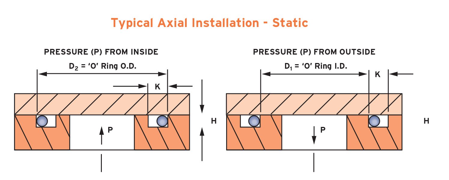
As important as the o’ring seal itself is the groove that the o’ring seats into. The groove must be designed to accommodate not just the o’ring size, but also its intended usage; be it dynamic or static operation, radial or axial loading, vacuum or high pressure.
The following information is a guide for o’ring groove dimensions for both static and reciprocating dynamic applications. The info is based on 70 Shore A Durometer hardness only.
Surface Finish
Generally surface finish for sealing surfaces are as follows…
63RMS maximum: For non-critical sealing surfaces such as groove sides
32RMS maximum: For static sealing on critical sealing surfaces such as groove base and top.
16RMS maximum: For dynamic sealing surfaces and for sealing gases in a face type seal.
Cylinder Groove Designs
Dimensions for o’rings used in static and dynamic applications for both radial and lateral loading.
Static Cylinder Grooves
| O’ring Cross Section | (L) Groove Depth Radial | (L) Groove Depth Axial | Squeeze Radial % | Squeeze Axial % | (E) Max Diametrical Clearance | G) Groove W 0 Back-up ±.005 | G) Groove W 1 Back-up ±.005 | G) Groove W 2 Back-ups ±.005 | R) Groove Radius | Max Eccentricity |
|---|---|---|---|---|---|---|---|---|---|---|
| .070 | .050 – .052 | .050 – .054 | 22–32 | 19–32 | .004 | .095 | .140 | .207 | .005 – .015 | .002 |
| .103 | .081 – .083 | .074 – .080 | 17–24 | 20–30 | .005 | .142 | .173 | .240 | .005 – .015 | .002 |
| .139 | .111 – .113 | .101 – .107 | 16–23 | 20–30 | .006 | .189 | .210 | .277 | .010 – .025 | .003 |
| .210 | .170 – .173 | .152 – .162 | 15–21 | 21–30 | .006 | .283 | .313 | .413 | .020 – .035 | .004 |
| .275 | .226 – .228 | .201 – .211 | 15–20 | 21–29 | .007 | .377 | .410 | .540 | .020 – .035 | .005 |
Reciprocating Cylinder Grooves
| O’ring Cross Section | (L) Groove Depth | Squeeze % | (E) Max Diametrical Clearance | (G) Groove W 0 Back-up ±.005 | (G) Groove W 1 Back-up ±.005 | (G) Groove W 2 Back-ups ±.005 | (R) Groove Radius | Max Eccentricity |
|---|---|---|---|---|---|---|---|---|
| .070 | .055 – .057 | 15 – 25 | .004 | .095 | .140 | .207 | .005 – .015 | .002 |
| .103 | .088 – .090 | 10 – 17 | .005 | .142 | .173 | .240 | .005 – .015 | .002 |
| .139 | .121 – .123 | 9 – 16 | .006 | .189 | 0.210 | .277 | .010 – .025 | .003 |
| .210 | .185 – .188 | 8 – 14 | .006 | .283 | .313 | .413 | .020 – .035 | .004 |
| .275 | .237 – .240 | 11 – 16 | .007 | .377 | .410 | .540 | .020 – .035 | .005 |
Face Seal Groove Design (Flange)
O-ring Groove Design Trelleborg
Dimensions apply to all laterally loaded o’rings in static face seal grooves for both liquid pressure and vacuum applications.
Groove Flange
| O’ring Cross Section | (L) Groove Depth | Squeeze (%) | (G) Groove W Liquid ±0.005 | (G) Groove W Vacuum ±0.005 | (R) Groove Radius |
|---|---|---|---|---|---|
| .070 | .050 – .054 | 19–32 | .101 – .107 | .084 – .089 | .005 – .015 |
| .103 | .074 – .080 | 20–30 | .136 – .142 | .120 – .125 | .005 – .015 |
| .139 | .101 – .107 | 20–30 | .177 – .187 | .158 – .164 | .010 – .025 |
| .210 | .152 – .162 | 21–30 | .270 – .290 | .239 – .244 | .020 – .035 |
| .275 | .201 – .211 | 21–29 | .342 –.362 | .309 – .314 | .020 – .035 |

Metric O’ring Groove Design
Featuring dimensions for metric cylinders and face seal (flange) grooves.
Metric O’ring Groove Dimensions
| O-Ring Cross Section | (L) Cylinder Groove Depth | (G) Cylinder Groove Width No Back Up Rings | (G) Cylinder Groove Width One Back Up Ring | (G) Cylinder Groove Width Two Back Up Rings | (L) Flange Groove Depth | (G) Flange Groove Width | (R) Radius without back up ring | (R) Radius with back up ring |
|---|---|---|---|---|---|---|---|---|
| 1.0 | 0.8 | 1.4 | – | – | 0.65 | 1.4 | 0.2 | 0.2 |
| 1.2 | 0.95 | 1.7 | – | – | 0.8 | 1.7 | 0.2 | 0.2 |
| 1.3 | 1.05 | 1.8 | – | – | 0.9 | 1.8 | 0.2 | 0.2 |
| 1.5 | 1.2 | 2.1 | – | – | 1.0 | 2.1 | 0.2 | 0.2 |
| 1.6 | 1.3 | 2.2 | – | – | 1.1 | 2.2 | 0.3 | 0.2 |
| 1.9 & 2.0 | 1.65 | 2.5 | 3.9 | 5.3 | 1.4 | 2.5 | 0.5 | 0.2 |
| 2.4 | 2.0 | 3.2 | 4.6 | 6.0 | 1.7 | 3.2 | 0.5 | 0.3 |
| 2.5 | 2.1 | 3.4 | 4.8 | 6.2 | 1.8 | 3.4 | 0.5 | 0.3 |
| 2.6 | 2.25 | 3.6 | 5.0 | 6.4 | 1.9 | 3.6 | 0.6 | 0.3 |
| 2.7 | 2.3 | 3.7 | 5.1 | 6.5 | 1.95 | 3.7 | 0.6 | 0.3 |
| 3.0 | 2.5 | 3.9 | 5.3 | 6.7 | 2.2 | 3.9 | 0.8 | 0.3 |
| 3.15 | 2.7 | 4.0 | 5.4 | 6.8 | 2.3 | 4.0 | 0.8 | 0.4 |
| 3.5 | 3.1 | 4.8 | 6.2 | 7.6 | 2.7 | 4.8 | 1.0 | 0.4 |
| 4.0 | 3.5 | 5.4 | 7.1 | 8.8 | 3.1 | 5.4 | 1.0 | 0.4 |
| 4.5 | 4.0 | 6.0 | 7.7 | 9.4 | 3.4 | 6.0 | 1.0 | 0.4 |
| 5.0 | 4.3 | 6.7 | 8.4 | 10.1 | 3.9 | 6.7 | 1.0 | 0.4 |
| 5.5 | 4.8 | 7.3 | 9.0 | 10.7 | 4.4 | 7.3 | 1.2 | 0.6 |
| 5.7 | 5.0 | 7.7 | 9.4 | 11.1 | 4.6 | 7.7 | 1.2 | 0.6 |
| 6.0 | 5.3 | 8.2 | 9.9 | 11.6 | 4.8 | 8.2 | 1.2 | 0.6 |
| 6.35 | 5.6 | 8.7 | 10.4 | 12.1 | 5.1 | 8.7 | 1.2 | 0.6 |
| 6.5 | 5.7 | 8.9 | 10.6 | 12.3 | 5.4 | 8.9 | 1.2 | 0.6 |
| 7.0 | 6.1 | 9.5 | 12.0 | 14.5 | 5.8 | 9.5 | 1.5 | 0.6 |
| 7.5 | 6.5 | 14.4 | 12.9 | 15.4 | 6.2 | 10.4 | 1.5 | 0.6 |
| 8.0 | 7.0 | 11.0 | 13.5 | 16.0 | 6.6 | 11.0 | 1.5 | 0.6 |
| 8.4 | 7.5 | 11.7 | 14.2 | 16.7 | 6.9 | 11.7 | 2.0 | 0.6 |
| 9.0 | 7.8 | 12.5 | 15.0 | 17.5 | 7.4 | 12.5 | 2.0 | 0.6 |
| 9.5 | 8.3 | 13.3 | 15.8 | 18.3 | 7.8 | 13.3 | 2.0 | 0.6 |
| 10.0 | 8.7 | 13.5 | 16.0 | 18.5 | 8.3 | 13.5 | 2.0 | 0.6 |
| 11.0 | 9.6 | 15.5 | 18.0 | 20.5 | 9.1 | 15.5 | 3.0 | 0.6 |
| 12.0 | 10.5 | 16.8 | 19.3 | 21.8 | 10.3 | 16.8 | 3.0 | 0.6 |
| 14.0 | 12.2 | 19.0 | 21.5 | 24.0 | 11.6 | 19.0 | 3.0 | 0.6 |
| 15.0 | 13.2 | 20.0 | 22.5 | 25.0 | 12.5 | 20.0 | 3.0 | 0.6 |
| 16.0 | 14.0 | 21.5 | 24.0 | 26.5 | 13.5 | 21.5 | 3.0 | 0.6 |
Dovetail Groove Designs
In a face seal, a dovetail and half-dovetail groove are ideal for holding an o’ring in place during installation and operation. This can allow more streamlined maintenance and shorter downtime with less effort required to secure the seal during installation. Especially handy if the face seal is assembled upside-down. However, due diligence is required when designing a dovetail groove due to limited void space compared to a conventional square groove. This problem can be aggravated by volume swell. Therefore dovetail grooves are not recommended unless end use conditions and their effects upon the seal are thoroughly taken into consideration.
Note: Top radius (R) is a critical dimension; too small a radius can damage the seal during installation, while excess radius can lead to extrusion failure.
Dovetail Groove
| O’ring CS | Groove Depth (L) | Squeeze (%) | Groove Width (G) | Retainer Radius (R) | Groove Radius (R₁) |
|---|---|---|---|---|---|
| .070 ±.003 | .053 – .055 | 23 | .057 – .061 | .005 | .015 |
| .103 ±.003 | .081 – .083 | 21 | .083 – .087 | .010 | .015 |
| .139 ±.004 | .111 – .113 | 20 | .113 – .117 | .010 | .031 |
| .210 ±.005 | .171 – .173 | 18 | .171 – .175 | .015 | .031 |
| .275 ±.006 | .231 – .234 | 16 | .231 – .235 | .015 | .062 |
| .375 ±.007 | .315 – .319 | 16 | .315 – .319 | .020 | .093 |
O-ring Groove Design For Vacuum
Half Dovetail Groove
| O’ring CS | Groove Depth (L) | Squeeze (%) | Groove Width (G) | Retainer Radius (R) | Groove Radius (R₁) |
|---|---|---|---|---|---|
| .070 ±.003 | .053 – .055 | 23 | .064 – .066 | .005 | .015 |
| .103 ±.003 | .083 – .085 | 19 | .095 – .097 | .010 | .015 |
| .139 ±.004 | .113 – .115 | 18 | .124 – .128 | .010 | .031 |
| .210 ±.005 | .173 – .176 | 17 | .190 – .193 | .015 | .031 |
| .275 ±.006 | .234 – .238 | 15 | .255 – .257 | .015 | .062 |
| .375 ±.007 | .319 – .323 | 14 | .350 – .358 | .020 | .093 |
Triangular Crush Groove Design
A static triangular crush seal groove is a simple design and ideal when space is limited and/or wall thickness is too thin for a conventional groove. It achieves the same sealing efficiency with either internal or external pressure. However there is very little void space and volume swell can easily lead to extrusion failure. O’rings in triangular crush grooves are permanently deformed once installed, therefore cannot be reused and are discarded after use.
Triangular Crush Groove
| Cross Section (W) | ± | Groove Depth (L) | ± (-0) |
|---|---|---|---|
| .070″ | ±.003″ | 0.092″ | +.003″ |
| .103″ | ±.003″ | 0.136″ | +.005″ |
| .139″ | ±.004″ | 0.184″ | +.007″ |
| .210″ | ±.005″ | 0.277″ | +.010″ |
| .275″ | ±.006″ | 0.363″ | +.015″ |
| 1.50mm | ±0.08mm | 1.98mm | +0.08mm |
| 2.00mm | ±0.08mm | 2.64mm | +0.08mm |
| 2.50mm | ±0.08mm | 3.30mm | +0.13mm |
| 3.00mm | ±0.10mm | 3.96mm | +0.13mm |
| 4.00mm | ±0.13mm | 5.28mm | +0.18mm |
| 5.00mm | ±0.13mm | 6.61mm | +0.25mm |
| 6.00mm | ±0.15mm | 7.93mm | +0.25mm |
| 8.00mm | ±0.18mm | 10.57mm | +0.38mm |
| 9.00mm | ±0.18mm | 11.89mm | +0.38mm |
Imperial PTFE O’ring Groove Design
Due to PTFE’s (Teflon®) highly limited deflection ability, the following table has suggested groove dimensions for open face seal (flange) type grooves using imperial PTFE o’rings. PTFE o’rings in radially loaded closed grooves are generally not recommended, however if this is unavoidable, PTFE o’rings can be heated to around 100°C to allow them to become slightly flexible, aiding installation.
| O’ring CS | Minimum Squeeze | Groove Width (G) |
|---|---|---|
| .070 ±.003 | .005 | .080 |
| .103 ±.003 | .006 | .110 |
| .139 ±.004 | .007 | .160 |
| .210 ±.005 | .008 | .240 |
| .275 ±.006 | .010 | .315 |